Installing the Milo pilot
How to install milo autopilot ?
The installation takes place in 3 main steps:
- Installation of the electronic control box inside the boat
- Attaching the pilot actuator to the tiller.
Connect the actuator to the electronic box.
Installation of the electronic control box:
Choose a location inside the boat, or at least protected from humidity. This location must be accessible, and as far away as possible from the metal masses of the boat, such as the engine. Especially avoid metal masses above or below the box.
Attach the box to the boat. The top cover must be able to be opened, and the interior of the case must be accessible. To fix the box, you can for example use the 2 pre-drilled holes visible in the bottom of the box.
Orientation of the case: the” long length” of the case must be parallel to the axis of the boat. The cover of the box must on top.
See these two diagrams beside for more clarity.


Connect the power cable to a 12V voltage source. Inserting a fuse is not necessary. The box includes a 6.3 amp glass fuse.
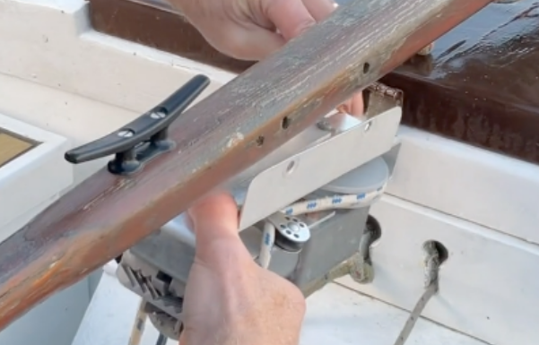
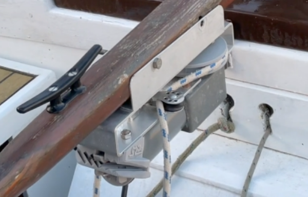
Attach the pilot actuator to the tiller.
The actuator must be firmly fixed below the tiller.
For example, the 2 fixing brackets supplied with the actuator can be used. The brackets have holes in the upper part. You can drill 2 holes 7mm in diameter in the tiller, facing the holes in the brackets, and use 2 stainless steel bolts (not supplied) which will pass through these holes. The distance between the brackets can be adjusted using their lower holes.
If you do not wish to pierce the tiller and if it is not too thick, you can just tighten the brackets on the tiller by passing 2 stainless steel bolts above the tiller. Another solution consists in not using brackets but stainless steel collars to hold the actuator on the tiller. Position these collars in the 4 existing notches on the upper plate of the actuator.


The front of the actuator must be at a distance from the rudder axis of between 60 and 90 cm. (see diagram).
The 2 snap hooks at both ends of the endless rope must be attached to the sides of the cockpit, behind the actuator. The front of the actuator must be at a distance between 15 and 30 cm from the attachment points of the snap hooks (see diagram). The snap hooks being fixed, the 2 black elastic ropes must be completely extended. The snap hooks can be attached by different means; for example by ropes attaching the snap hooks to the holes in the strake, or to the pushpit (as in the video), or better still: to correctly placed padeyes.

Connect the actuator to the electronic control box.
- The actuator and the electronic box each carry a 5-conductor electric cable. These 2 cables must be connected using the sockets present at their end.
- The cable socket of the electronic box is intended to be installed on a wall of the boat facing the outside. The hole to be made in this wall must be 16 – 17 mm
If electrical wires have to be removed to allow this installation, care must be taken to refit them in the same position. The black conductors of the cable are numbered (from 1 to 4). The sockets are numbered 1 to 5. Match the wire numbers to the socket numbers. The yellow-green wire is mounted on number 5 of the socket. The electronic card input terminal block also has numbers 1 to 4, and a YG input for the yellow-green wire.


- Contact: contact@milo-autopilot.com
- Links
